CO₂ capture process - Climate-neutral power plants
Our innovative technology of a climate-neutral combined heat and power plant can be read in the digital magazine:
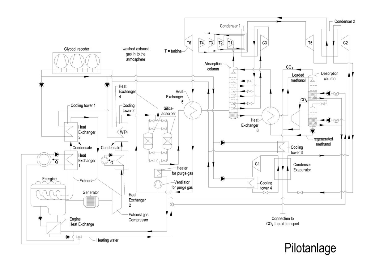
CCS-compatible CO₂ capture process
Step 1
The exhaust gas from the engine or turbine of the CHP unit, which exits at high temperatures (from internal combustion engines between 500° and 600 °C hot, in gas turbines the exhaust gas is even hotter) is cooled in three stages:
In the 1st stage, the exhaust gas is used in a heat recovery steam generator for the production of saturated steam at 2 bar and 120 °C. The saturated steam is needed to provide the heat of solution required for desorption of the CO2 in process step 5.
In the 2nd stage, the waste gas is further cooled in a waste gas heat exchanger and the heat is used energetically for heating the building.
In the 3rd stage, the exhaust gas is further cooled with cooling water. Depending on the season, cooling of the exhaust gas to a temperature range between +5 °C and +30 °C can be achieved.
In process step 1, a large part of the water vapor contained in the exhaust gas condenses and is separated as condensate.
Step 2
In process step 2, the cooled and dried exhaust gas 2 is compressed and cooled in stages to the cryogenic process temperature. The level of compression must be selected so high that the cold required in the process can be generated during expansion of the waste gas freed from CO2.
The heat generated during compression can be used energetically for heating purposes during recooling down to the return temperature of the heating network with the aid of exhaust gas heat exchangers. Further cooling of the compressed exhaust gas is achieved with cooling water. During flue gas cooling at higher pressure, a further part of the water vapor contained in the flue gas condenses and is separated as condensate.
In the next cooling stage, the compressed exhaust gas cooled to cooling water temperature is cooled to the process temperature of the CO2 absorption column of approx. 235 °K and the exhaust gas temperature falls below the freezing point of water.
As a saturated, moist exhaust gas, the exhaust gas still has a considerable water content, which is, for example, approx. 1.70 g of steam per kg of exhaust gas at 25 °C and 12 bar. When the exhaust gas is cooled below the freezing point of water, the water vapor contained in the exhaust gas condenses or freezes out. Without cleaning measures, the heat exchanger would clog in process step 2. To avoid this clogging of the heat exchanger, self-cleaning heat exchangers are required to cool the exhaust gas or other measures are required to dry the exhaust gas. In self-cleaning heat exchangers, the ice deposited on the walls of the heat exchanger during exhaust gas cooling and the condensed water are absorbed by the CO2-free exhaust gas discharged into the atmosphere by periodically switching the flow, thus cleaning the heat exchanger again. Self-cleaning heat exchangers are well-known components from air separation plants.
Step 3
In process step 3, the cooled exhaust gas is introduced into an absorption column. In the absorption column, the CO2 in the exhaust gas is physically absorbed by washing with a solvent. Methanol is particularly suitable as a solvent. At the process temperature in the absorption column of 235 °K, methanol acts as a selective solvent for CO2.
The absorption of the CO2 is isothermal, i.e. the heat of solution of the CO2 must be dissipated. Refrigerant evaporators are built into the absorption column for this purpose.
At the top of the absorption column, the scrubbed exhaust gas, free of CO2, is removed. On the sump side, the methanol loaded with CO2 is removed from the absorption column.
Step 4
The methanol loaded with CO2 is fed to a CO2 desorption column, which has a 2-stage design: the pressure stage, which is operated at the process pressure of the absorption column, and the low-pressure stage of the CO2 desorption column.
In the pressure stage of the CO2 desorption column, the methanol/CO2 mixture is heated up to a maximum of the boiling temperature of the methanol. Due to the temperature increase, the solubility of the CO2 in methanol decreases and most of the absorbed CO2 is released with the addition of the heat of solution. The CO2 leaves the pressure stage of the CO2 desorption column at the top.
The partially depressurized methanol collects in the sump of the pressure stage of the CO2 desorption column and from there is fed via a throttle valve into the low-pressure stage of the CO2 desorption column. The pressure reduction further lowers the solubility of CO2 in methanol and an additional portion of the absorbed CO2 is released with the addition of the heat of solution.
The solution heat for desorption of the CO2 is provided from the exhaust heat of the engine or turbine according to process step 1.
Step 5
In process step 5, the desorbed CO2 from the low-pressure stage is compressed in a CO2 compressor to the pressure of the pressure stage and combined with the desorbed CO2 from the pressure stage.
The combined CO2 14 is precooled by heat transfer to the CO2-laden methanol and then liquefied by heat transfer to a boiling refrigerant in a condenser evaporator. Subsequently, the liquid CO2 is compressed to the required pressure by a high-pressure pump and stored in an underground CO2 storage facility.
Step 6
In process step 6, the CO2-free exhaust gas taken from the head of the absorption column is expanded in expansion turbines to perform work. This expansion provides the refrigeration required in the refrigerant condenser.
Depending on the refrigerant used, temperature limits must be observed below which the outlet temperature from the expansion turbines must not drop. If, for example, ammonia is used as the refrigerant, the temperature must not fall below the ammonia melting point of 195 °K, which means that a 4-stage expansion is required in the calculation example.
On the one hand, the condensed refrigerant is evaporated in the refrigerant evaporators of the absorption column and a second part of the liquid refrigerant is used in the condenser evaporator for CO2 liquefaction.
Thus, for CO2 liquefaction at a CO2 pressure of 12 bar and a CO2 condensing temperature of 238 °K, the CO2 condenser evaporator can be operated with boiling ammonia as refrigerant at 0.8 bar and 235 °K.
The CO2-free exhaust gas expanded in the turbines is subsequently used in the self-cleaning heat exchanger to cool the exhaust gas in process step 3. In this process, CO2-free exhaust gas absorbs the ice deposited on the walls of the heat exchanger during exhaust gas cooling and the condensed water from process step 3 by periodically switching the flow, and the CO2-free exhaust gas is subsequently emitted into the atmosphere with the absorbed water in a climate-neutral manner.